Voltage drop across inductor formula
The above is the same formula used in electrostatics. In this case the current flowing through each inductor is the same while the voltage across each inductor is different.
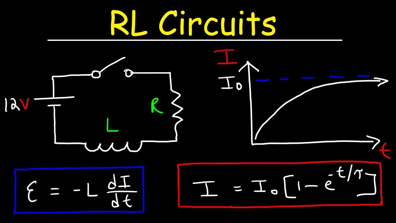
Rl Circuits Inductors Resistors Youtube
So for 2 lines 2 100 ft.

. DC voltage drop formula Voltage drop Calculation in AC Circuits. Also often referred to as a Howland current pump this configuration has. Use the formula L VTonIpk to calculate the inductance.
When either type of component is placed in an AC circuit and subjected to oscillating signals it will pass a finite amount of alternating current. Figure 411 shows a classic voltage to current V-to-I converterThe resistor values can be selected such that the output current in the load varies only with the input voltage V IN and is independent of the loadThe circuit is widely used in industrial instruments for supplying a 4 to 20 mA signal for example. I T I 1 I 2 I 3 and we know from the previous tutorials on inductance that the self-induced emf across an inductor is.
Because the conductors or plates are close together the opposite charges on the conductors attract one another due to their electric fields allowing the capacitor to store more charge for a given voltage than when the conductors are separated. It is as follows. The solution to solve this problem is to rectify the capacitive or the inductive factor by using inductor or capacitor banks.
For DC closed circuits we also use Kirchhoffs circuit law for voltage drop calculation. Energy stored in a capacitor. The voltage drop across DC power line is simply calculated by Ohm law ie.
The flow of electric current creates a magnetic field around the conductor. X L is the inductors. The voltage drop across a particular resistance is governed by the current and the resistors resistance value.
Supply Voltage Sum of the voltage drop across each component of the circuit. One can find the voltage drop across a resistor simply by using Ohms law of current electricityIn another article we have discussed different ways to find the voltage drop across a capacitor as well. Voltage drop across Resistors in Series and Parallel circuits.
Here we are taking an example of a 100 ft power line. Is path-independent and there is a well-defined voltage across the inductors terminals. The inductive reactance formula can be derived as.
That usually eliminates the voltage drop. By using Kirchoffs voltage law total voltage drop is the sum of the voltage drop across each inductor. Inductor current lags inductor voltage by 90.
The formula surface as well as the voltage greater or lesser than all must be included. R2 Voltage drop 08 X 5 4 volts. Using ohms law we can find how much voltage a resistor reduces by dropping voltage across it as long as we know the supply voltage and total resistance.
Suppose the voltage drop across the inductor is calculated at approx 50mV. The voltage drop across the inductor is expressed in terms of current and the voltage drop across the capacitor is where Q is the charge stored on the positive plate of the capacitor. They create a voltage drop directly proportional to the rate of change in current.
An LC Circuit Now according to Kirchhoffs voltage law the sum of potential drops across the various components of a closed-loop is equal to zero. XL 1 2πfL XL is an inductive reactance measured in Ohms Ω π 3142 a numeric constant. V I x R R V I R 005 1 R 005 ohm How to reduce the DCR while constructing the Inductor.
This voltage depends upon the inductance value. Parallel plate capacitor with dielectric. Conductance is proportional to how much flow occurs for a given pressure and resistance is proportional to how much pressure is required to achieve a given flow.
When the current flowing through the coil changes the time-varying magnetic field induces an electromotive force emf in the. Otherwise there will be flickering. If we were to plot the current and voltage for this very simple circuit it would look something like this.
The entire short line model is an open circuit in this condition and no current flows in an open circuit so I 0 A and the voltage drop across the line given by Ohms law V line drop IZ line is 0. In this article Im going to explain the formula and polarity of the. Since we started at a capacitor voltage of 0 volts this increase of 14989 volts means that we have 14989 volts after 725 seconds.
For example if the lamp boards input voltage is 37-40V and the input current is 300mA the LED driver output voltage can be selected to include it and the current is nearly the same. V L1 V L2. R1 Voltage drop 08 x 10 8 volts.
Inductors in Parallel have a Common Voltage across them and in our example below the voltage across the inductors is given as. He adjusts frequency so the voltage drop due to the impedance V drop of resistance. This then becomes Z 2piFL R so L R2piF.
In the voltage regulation formula V no load is the voltage measured at the receiving end terminals when the receiving end is an open circuit. An inductor also called a coil choke or reactor is a passive two-terminal electrical component that stores energy in a magnetic field when electric current flows through it. Our universal formula for capacitor voltage in this circuit looks like this.
The voltage drop across all of the inductors in parallel will be the same. So after 725 seconds of applying a voltage through the closed switch our capacitor voltage will have increased by. This integral with the path of integration being along the test leads is what a voltmeter will actually measure.
An inductor typically consists of an insulated wire wound into a coil. Once we know the frequency and voltage of the AC supply utilize them through the voltage divider law to get the voltage drop across every inductor is shown below. Then the DCR of that inductor can be calculated as.
Three basic passive circuit components Resistor Capacitor and Inductor are known to all. Voltage across an Inductor in AC circuit. Connect the inductor coil to a pulsed voltage source.
After passing the current the voltage drop across the leads of the inductor has to be measured. The following formula is used for calculation. Here three inductors and are connected in series.
All of the numbers needed should be right there on the oscilloscope. The field strength depends on the magnitude of the current and follows any changes in current. Remember the voltage dropped across an inductor is a reaction against the change in current through it.
As the time passes the current gradually increases and the magnetic field also builds up. Inductance is the tendency of an electrical conductor to oppose a change in the electric current flowing through it. In the hydraulic analogy current flowing through a wire or resistor is like water flowing through a pipe and the voltage drop across the wire is like the pressure drop that pushes water through the pipe.
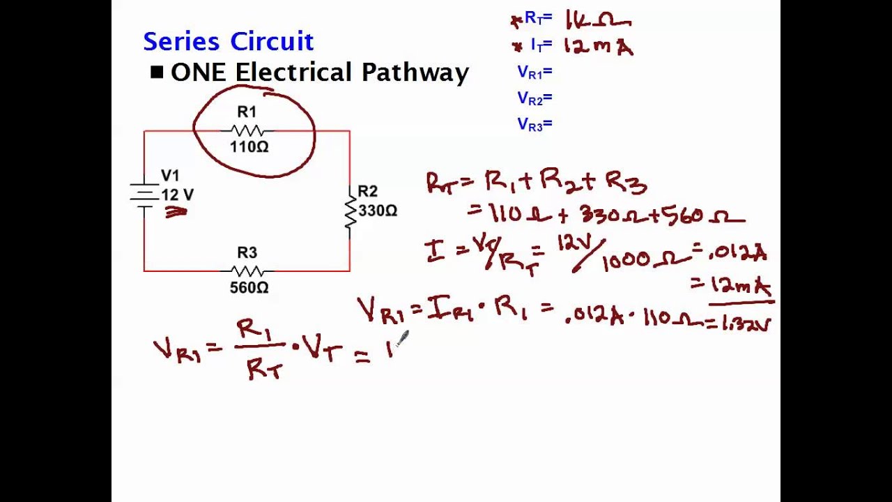
In which the current is zero there is a positive maximum voltage across the inductor. The result is that the smaller 10mH inductor has less reactance 1256Ω so therefore less of a voltage drop at 30 volts compared to the larger 20mH inductor which has a reactance of 2514Ω and a voltage drop of 40 volts respectively. EqVRI eq that calculates three voltages that correspond to three different resistors but.
The voltage drop is the difference between the two readings. The rate at which an inductors current may change is directly related to the amount of electromotive force voltage impressed across the inductor. Low current is acceptable.
The inductive voltage. Formula for capacitance of different type capacitors. Voltage Drop Calculation of a DC Power Line.
1- Using Ohms law the voltage drop across resistors in series can be calculated by the formula. A capacitance of one farad F means that one coulomb of charge on each conductor causes a voltage of one volt across the device. The amount of voltage drop across each inductor is proportional to its reactance.
V T V 1. Pure inductive circuit waveforms.

Capacitors In Series And Series Capacitor Circuits

Can The Voltage Drop Across The Inductor Or Capacitro In A Series Lcr Circuit Be Greater Than Youtube

Voltage Dividers And Voltage Division Circuits

Rl Circuits Inductors Resistors Youtube

Voltage Dividers And Voltage Division Circuits
Calculating Voltage Drop Across Resistors Youtube

Reactance Resistance Impedance What S The Difference Video Khan Academy

Voltage Across Inductor Bartleby

How To Calculate The Voltage Across An Inductor

Inductive Reactance Reactance Of An Inductor

Ac Inductance And Inductive Reactance In An Ac Circuit

Voltage Dividers And Voltage Division Circuits

Ac Voltage Across Pure Inductor Derivation Video Khan Academy
In Series Lcr Circuit Voltage Drop Across Resistance Is 8v Across Inductor Is 6v And Youtube

Can The Voltage Drop Across The Inductor Or Capacitro In A Series Lcr Circuit Be Greater Than Youtube
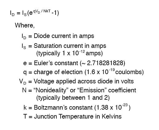
Introduction To Diodes And Rectifiers Diodes And Rectifiers Electronics Textbook
Why Is There A Voltage Drop Across Inductor Quora